Step 6: Metal parts
Preparing the suspensions
These kits comprise many metal parts, and they need a different treatment that the resin or plastic ones. On the other hand, when considering the suspension parts, wheels, etc, each assembly will need a special attention
The most critical is the suspension assembly, since its parts will be of great importance for the position of the model over a support surface. It’s not convenient to take as guide the shape of the parts the kits supply, the metal ones may bend since it’s is soft, and the resin ones usually show casting flaws.
So, the alignment and suspensions height should be checked, in fact something tedious as it means to test fit and check every aspect before gluing parts together, intending sometimes with white glue, just to check the components position, this nearly means the construction of the whole kit; however, there are some tips that could help to make things easier.
All metal parts of the 2002. There’s so much work in front, as we’ll see along the followings steps.

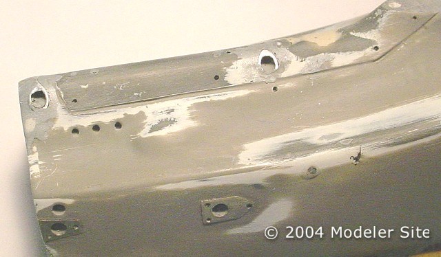
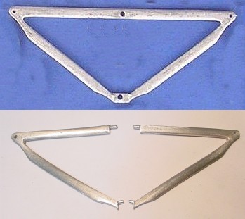
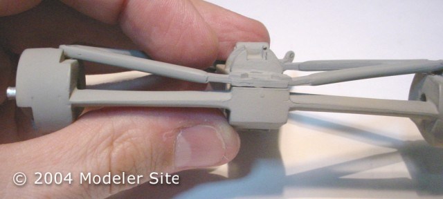
In step 2 of part II, I had explained how I modified the lower part of the monocoque to make it look realistic. Now, this means that some changes should be done to the lower arms of the front suspension. Both triangles are provided in only one part, as the picture in blue background shows
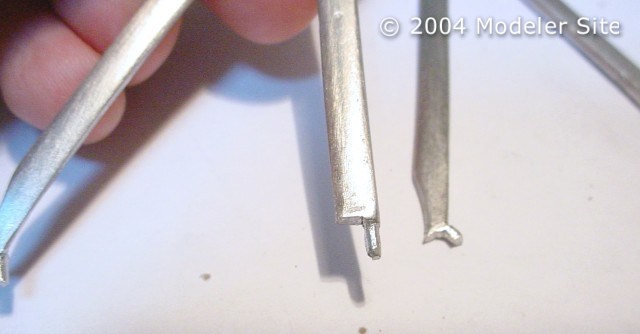
It’s no longer possible to assemble them in that way, so, this required to get them cut and filed so that their ends could penetrate the aluminium tubes of the monocoque. It’s quite a laborious task, but as it’s a very visible area of the model, it would be very notorious “that something is wrong”, if we don’t do this.
Once they’ve been placed, check that the front track keeps the same width as before.
This is only an example of which kind of changes can be achieved to improve these kits, this modification was done to both, the 2002 and 2003.
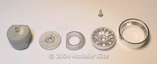
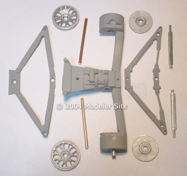
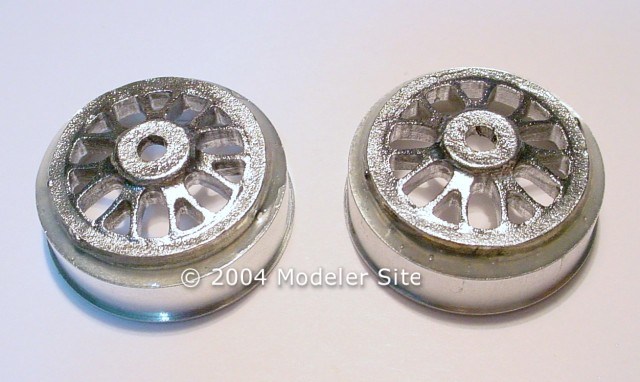
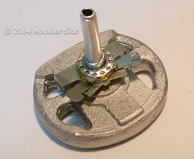
Here you have, the upright of the 2003 rear suspension and other components that belong to the wheel assembly.

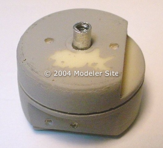
The way the manufacturer decided to hold the wheels didn’t seem convincing to me, I wanted to use scaled wheel nuts, I scratch a master and made resin copies . So, I placed 3 mm aluminium tubes, which should be perfectly aligned, to be glued with CA. These tubes have to be inserted just 5 mm inside the upright, and will be aligned placing the disk brake and the wheel centre. You can appreciate a front left upright (which has been primed) with the tube already placed.
These are the parts needed to do the alignment, look at the parker conical head screw provided with the kit, which was used to hold the wheel. It was perfectly screwed in the 3 mm tube.
How the assembly would look before screwing the wheel.

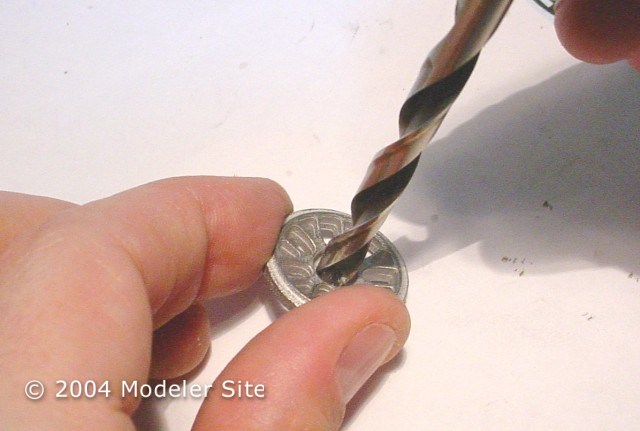
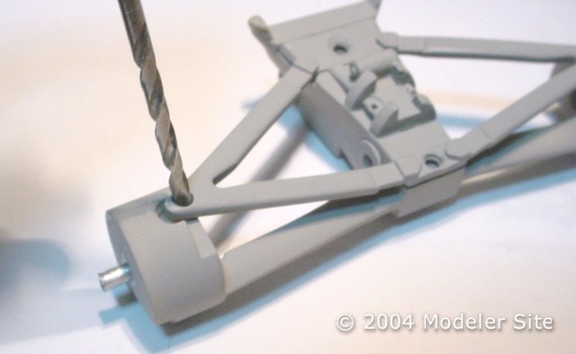
As the head of the screw is conical, and I wanted to get it hidden in order to glue over it a resin nut, I tried this hole gently with a drill in hand.
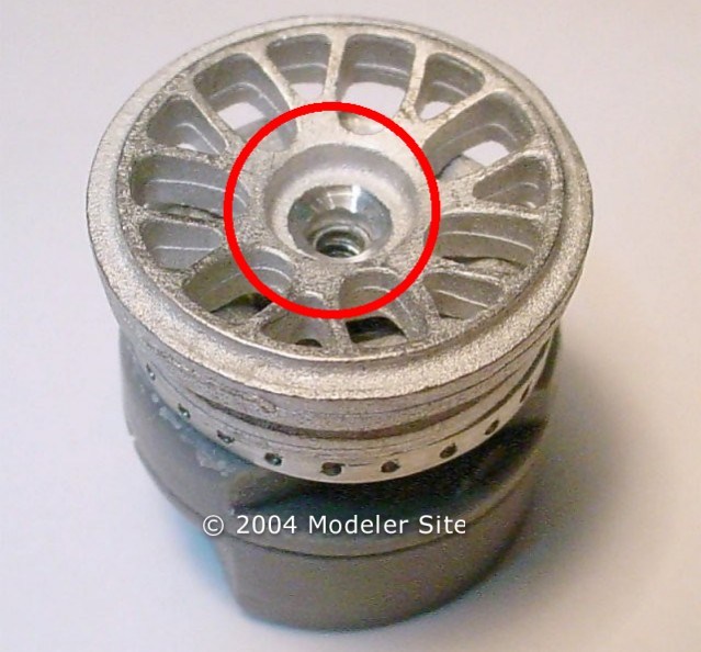
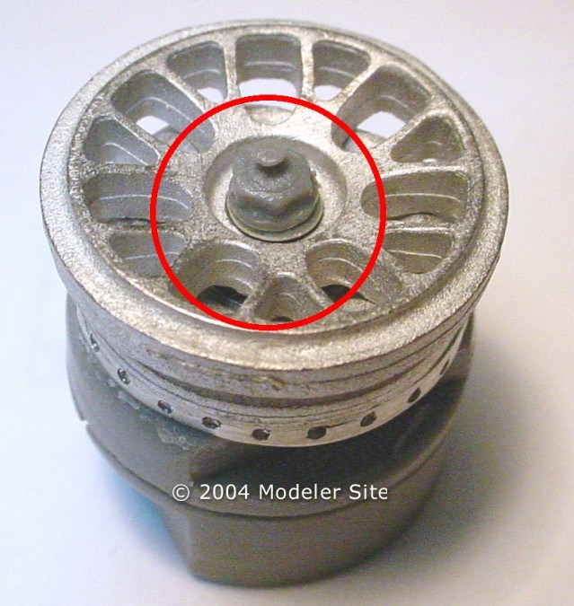
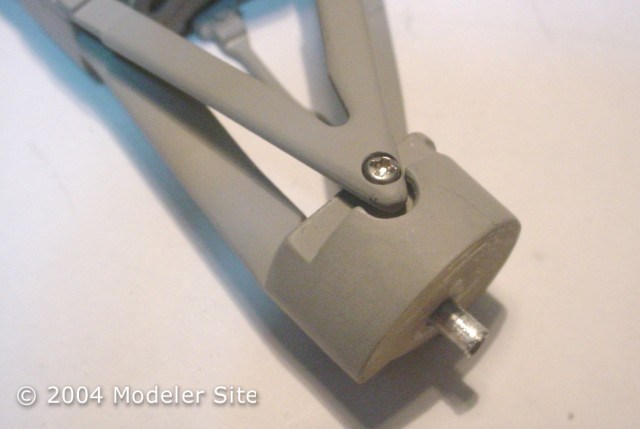
In the red circle, you can appreciate how I drilled the edge of the hole to a conical shape.
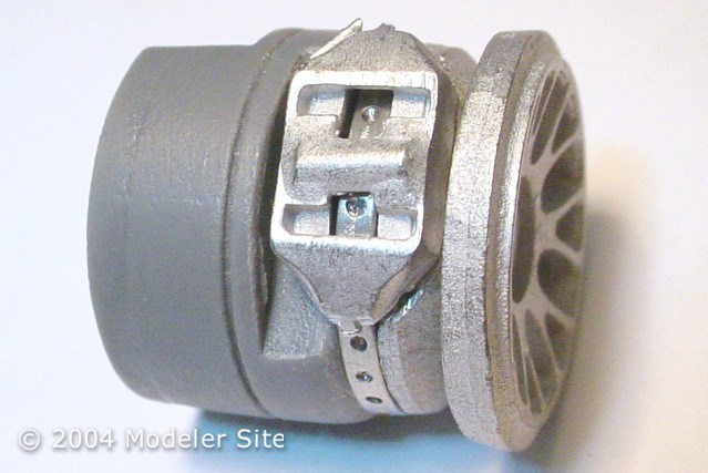
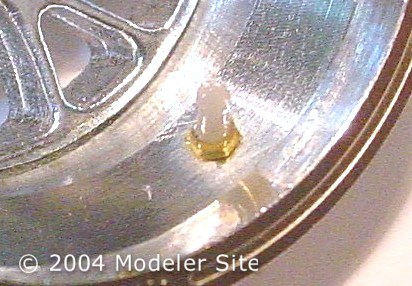
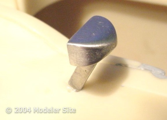
Here you see the screw at the level of the wheel centre.
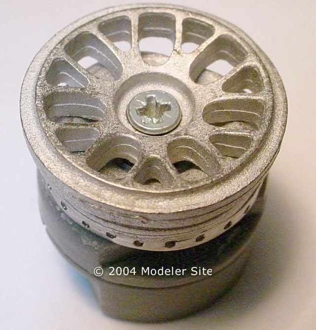
The resin nut posed in its definitive position. Once all the parts are painted, it will be added with white glue. Note, that the screw looks like a lock washer, giving to the whole more realism.
To complete this assembly, we should have to add the tire and half of the ring wheel.

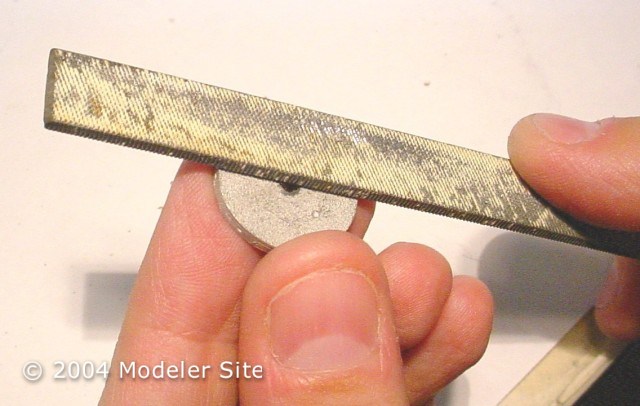
The brake disks are being treated, here filing the back face to get it flat.
The mould marks are being removed with a file and the disk mounted in an electric screwdriver. In this case I used a Black & Decker, to take more control, ( I used a pin vise I bought separately).
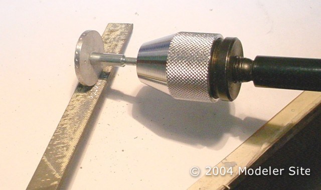
To get a smooth surface the same task was achieved but this time on a (3M) sand pad.

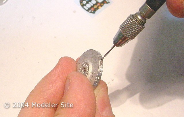
The vent holes with 1 mm drill are being made.
Finished assembly, it was tested for all the wheels.
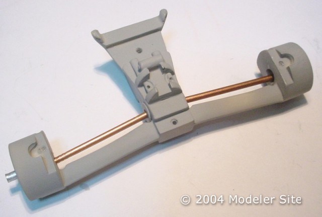
It was time to prepare the rear suspension. Here you can see the associated components with the gear box and (two) 3 mm pieces of wire or cooper tube, which represent the half shafts.
The mould marks are removed by using small files, this job should be done without pressing too much to avoid making deep marks.

The finished part has been sanded and polished, before priming. I recommend to airbrush Humbrol matt enamel, very diluted.
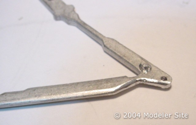
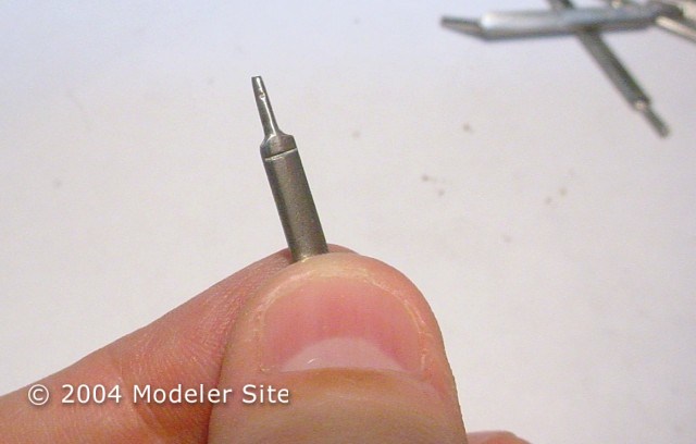
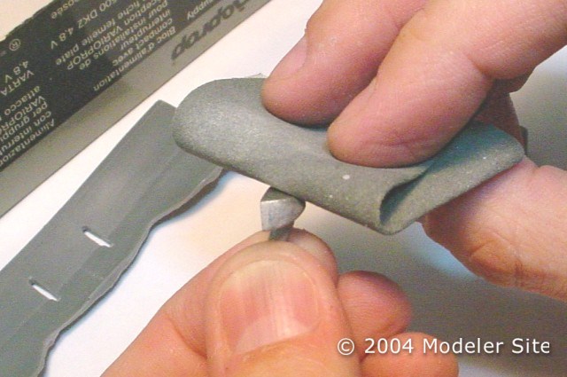
Certain parts, such as the ends of some arms, should need to keep the metal look. After the mould marks were removed, we began sanding with #8000.

Later, they were polished with Tamiya compound, but any non caustic metal polisher could have been useful.
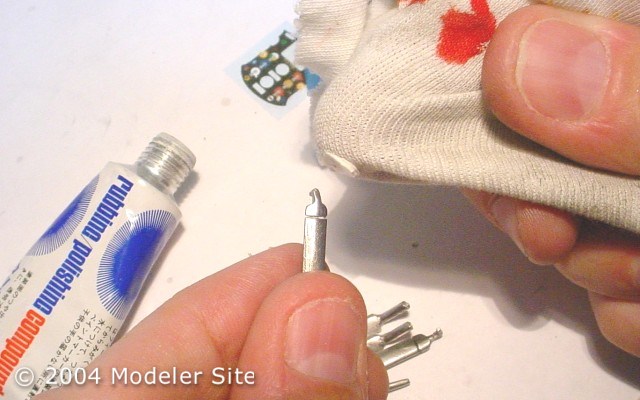
Final look after the polishing session. Generally, metals tend to turn darken, so It would be better to give a Model Master sealer coat or just a silicone coating.
We start to position the parts temporary, to make the drillings where the screws or support pins will be placed, or you may considerer the most convenient procedure.
I decided to use screws from my spare box, and so, I went on making the necessary drillings for them. It’s important that the part takes a right position under your consideration. Farther on, we’ll make a final arrangement. The screws used for the arms ends should be thinner than the corresponding holes, to allow certain looseness and a later adjustment.

Like in the wheels case, here some holes are being given a conical shape.
Others should be enlarged (without passing through!!!), so that the screw head can be inserted and allow the PE(s) the kit supply, can be used.
Screw placed, note how the hole diameter in the upper part of the wishbone, is larger in part of the section, and let that the screw head remain at a same level.
The location of the half shafts is tested.
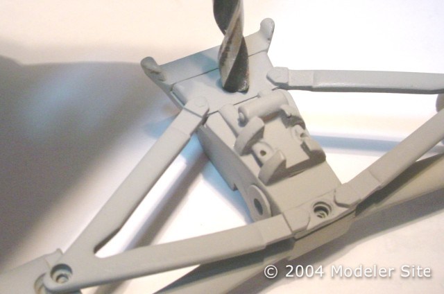
Drilling procedure and inferior wishbones checkup.

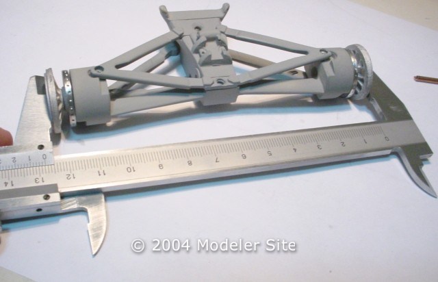
Look of the whole assembly, the parts have been primed and assembled to be aligned and checked that fit is perfect. Note that the centres of the wheel have been screwed for alignment purposes.

With the help of a measurement tool, the track and camber were checked. If some modifications were necessary, they should be made once the parts would have already been painted, loosening the screws and forcing the wheels to the right position, then they will be adjusted again and applied CA to fix their definitive position.
The centre of the wheel glued to the rings with two components epoxy.
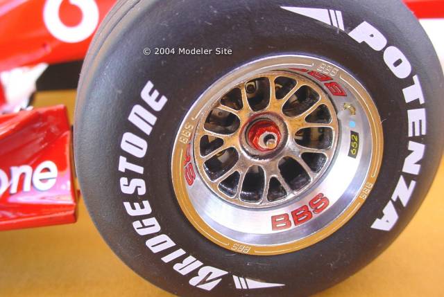
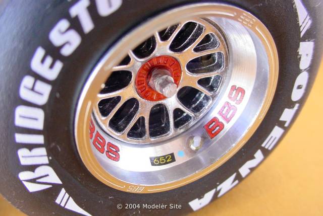
The wheel was ready, the centre has been painted Alclad HPA and PE with the BBS logos and a scratchbuilt valve were added.
Nuts that belong to the wheel of the 2003, the kit doesn’t supply a good replica of the nuts which are a new design in the real car. The ones on the left wheels should be painted clear red, over silver, and the ones on the right, clear blue.
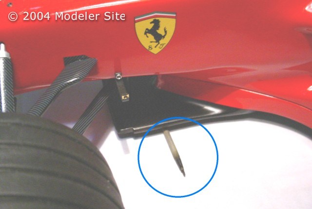
Look at the blue circle in the picture, the suspensions height has been adjusted by placing a toothpick under the undertray. This should be done prior to painting (although it’s tedious to build everything temporary) and tested at the moment of the suspensions final assembly.
Other metal parts
The rear view mirrors are being treated with a small file, not only to remove the mould marks but to give them the proper shape if necessary.

This job ends with Micromesh sand #3800.
The mirror has already been glued to the resin body, with CA. Note that I decided to prime and paint both mirrors, once they had been glued to the body.
Lastly, other metal parts were arranged, in this case the steering wheel. Several tube sections of different length were placed and the PE parts were glued one by one with CA.
Then, the aluminium tube (which should have to be mounted to the one on the monocoque) is masked, primed and painted semi gloss black.
To do the decoration, carbon fibre decal or clear yellow or green pieces of acetate sheet can be used.
The “handles” may be hand painted matt black.
The details were painted with the help of a magnifier and a #000 point brush. Heavy paint should be used, that’s to say with no dilution, and should be placed over the push bottoms and dials without being spread.

To be continued…