Tips for building the SE. 5a from Wingnut Wings 1/32 scale
by Michael Capell
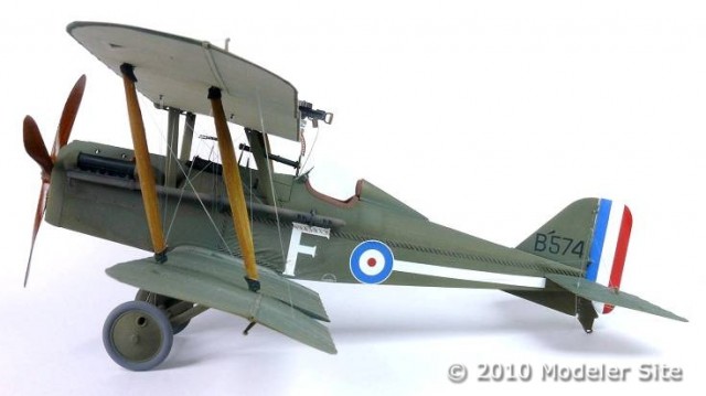
Well who saw this coming? Right out of the blue Wingnut Wing enter centre stage with no less than four original releases and all in 1/32 scale, incredible . When this company first appeared last year there was no fanfare or announcements, they just open a first class web site and sat back to see what happens. I can imagine the enjoyment they got seeing the surprise and amazement this created. For this article I chose the SE 5 from the four models available, reason being this one is the simplest to build and paint.
The kit molding is exceptional, especially the refined stitching along the wing tapes. Also we have a choice of fuselage options one pair having a pronounced fabric wrinkle effect and the other without, both styles appear in photographs from that period.
Another decision has to be made which of the five decal schemes to go for, in this case I went with option A, Lt. T.V. Lord no particular reason other than I wanted this model to have a four bladed propeller and not from a training unit.
Prior to any model build I always study the plans to avoid any pitfalls. Except these are in full colour and include close up pictures of the actual aircraft throughout to build, a helpful touch.
The item can be found at HobbyLink Japan > 1/32 Wingnut Wings SE. 5a “Hisso”
The wooden
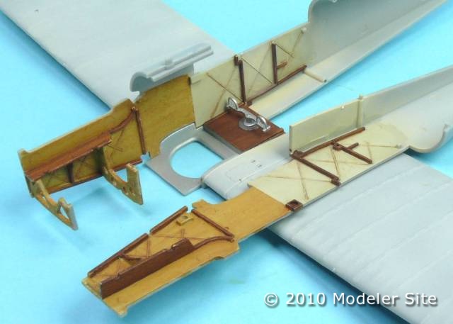
It be nice if wood effects could be made simple. Because if you are into WW1 aircraft this is one method you will be using from time to time. First we need a base colour to work on, most of the time I would use a light sand/ beige which is perfect for both light and dark wood effects. Once dry this needs to be sealed in with a couple of coats of acrylic gloss varnish this helps prevent the oil paint from staining the base colour.
A lighter base colour is required before starting the wood graining in this case Xtracolor XA1818 interior cream. Then sealed in with an acrylic gloss varnish
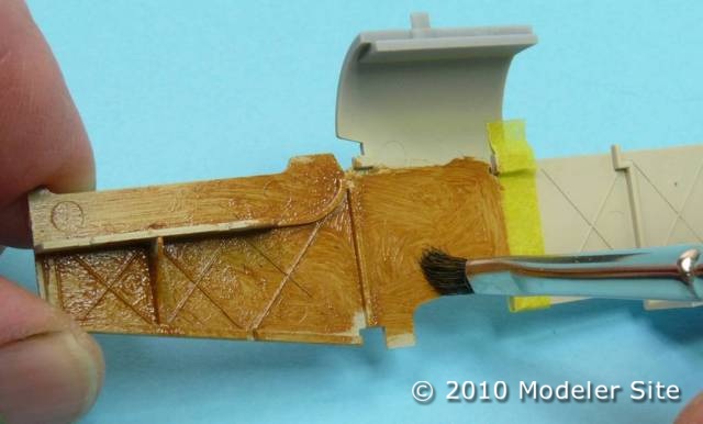
I have been using oil paints to simulate wood effects for years and have always achieved a reasonable result in no time at all. Using a flat stiff bristled brush apply the oil paint to the surface making sure the whole area is covered. Then remove any excess paint from the brush on to a paper towel.
Now we can start to drag to brush in the direction of the grain again continuing to remove any excess paint from the brush. Finally once a wood grain appears I like to blend the grain together using a soft haired flat brush to finish off.
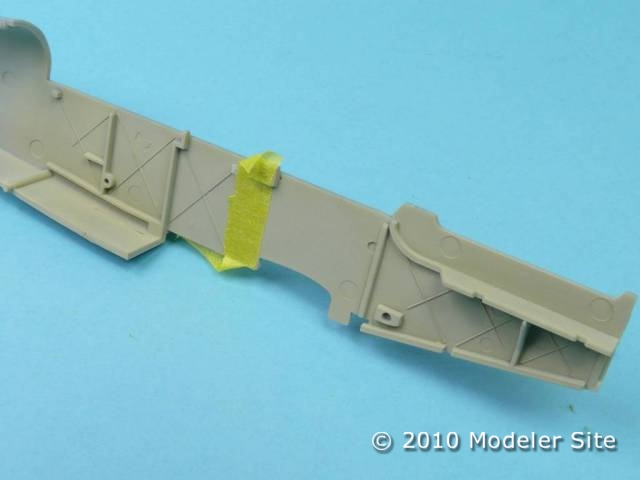
Once the area has been masked the oil paint is brushed on. Then the graining can begin by simple dragging the brush in one direction and wiping off any excess from the brush as the effect is built up
One advantage of using oil paint is its slow drying time allowing us to produce this effect. However this is also drawback as it takes nearly a week to dry fully dry, but since this is not a race I can get on with other stages in the mean time.
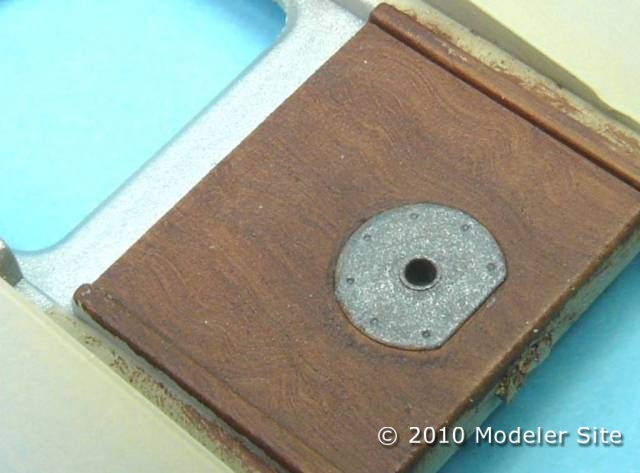
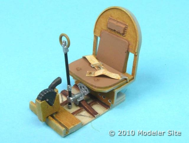
The cockpit floor is made with a darker hard wood which painted using a darker oil paint. This time the brush is moved from side to side as the brush is moved along the wet paint, producing a realistic finish.
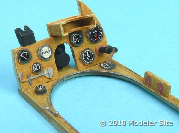
The overall effect is effective and relatively easy to master, even on larger areas. Just make sure that the oil paint is removed from any areas that needs to be glued or it will not stick!
Once it has finally dried I airbrush it with matt varnish (Xtracolor). Then any further painting and detailing can be carried out. The gauge decals received a drop of gloss varnish simulate the glass this also adds another dimensional aspect to the model.
Using a smaller brush even the small wooden cross members on the cockpit floor can be grained . Any mistakes can be removed using a clean brush dipped in white spirit. Just visible under the seat are the holes for the control cables.
A pity most of this will be hidden, but it is satisfying seeing peoples reaction when you tell them it is only paint! The control cables made from stretched sprue and painted using a black marker pen.
Painting : any Colour as long as it is green
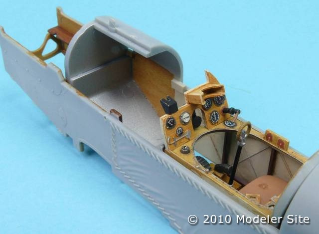
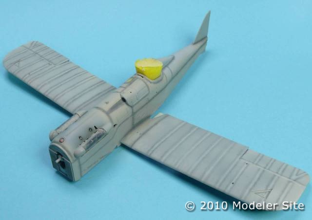
With out adding to controversy over the correct shade for PC 10 I decided to use Xtracrylix RAF green. The reason for this comes from a visit to Duxford museum and their various Biplanes on show. The finish to me look more green than the brown/ green shade of PC 10 so I went with that interpretation. Prior to painting the cockpit is temporally plugged with soft foam sponge and the Vickers access panel (A68) is glued temporarily in place using a couple of dots of PVA glue, this allows the gun to be added later on after all the painting is finished.
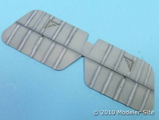
Attempting to make this single colour more interesting some pre- shading and highlighting is needed. Using a dark grey for the shading this is airbrushed along any panel lines and wing tapes. Next the rib tapes require highlighting with white which is sprayed at a lower pressure helping to reduce any over spray.
All the shadows and highlights are done free hand. Which is obviously a lot quicker than having to tediously mask everything, and good practice in learning to control your airbrush.
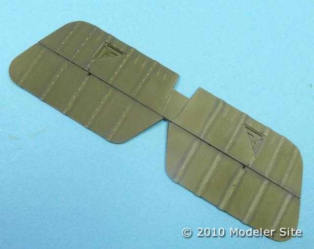
Using Xtracrylix RAF Green (XA1001) and thinned with their own brand thinners, this is airbrushed in several light coats. Always start spraying slightly off the model then move the spray across the model surface and finish just after the spray has left the model.
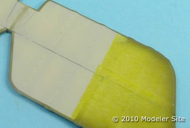
The undersides have a narrow boarder of green surrounding the wings. This is masked using the wing as a template held firmly in place over Tamiya tape and then cut using a new scalpel blade.
Here is the result after cutting and adjusting the mask to get the perfect border.
The clear doped linen (CDL) being the lightest colour is sprayed first, with Xtracrylix German Interior cream . Then using the wings as a template a mask is cut out just a few millimeters smaller to allow for the green border around the outside edge of the wings and stabilizers.
To preserve the effect of the shading and highlighting I tend to thin the paint more than normal and build up the colour gradually. This method does take longer but allows you to make decisions on exactly how you want the model to look, remember once its on it cant be removed!
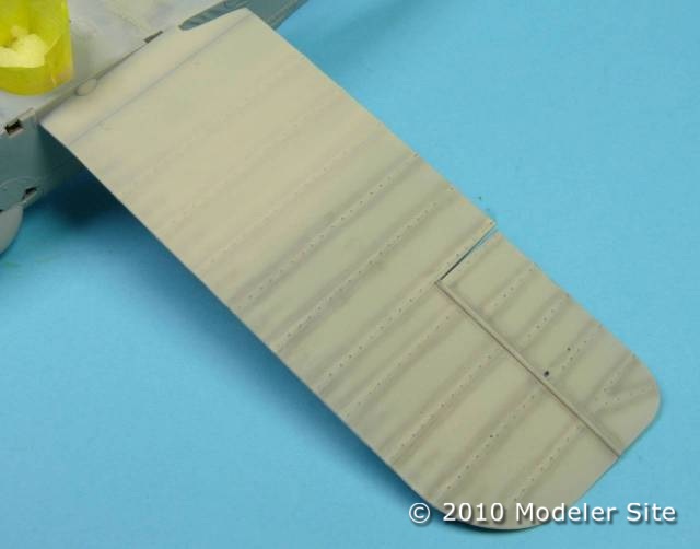
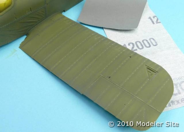
For some reason during spraying the surface appeared rough, so using some polishing cloth to smooth it out it had the unexpected use of subtle highlighting along the wing tapes and stitching. A complete accident but something I will experiment with in the future.
Repeating same process is repeated for the main wings. This actually took less time as I had the method already perfected on the tail. Except I substituted cheaper decorators tape to fill in the majority of the wing area.
I always double check everything is masked. Soft sponge is ideal for filling in the cockpit and cling film is placed around the engine covers then poked into the gap between the engine and cowling using a cocktail stick.
Trial and error sometimes produce surprises. Whilst spraying I noticed some rough areas, so these were sanded smooth using a polishing cloth. Which had the added advantage of highlighting all the stitching along the wing tapes.
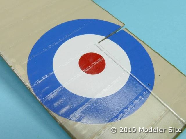
The next stage involves applying the decals over a gloss surface. A couple of brush coats of my dwindling stock of Johnsons Klear and I was soon ready for the decals. These soon snuggle down perfectly with Micro Sol solution and left over night to cure. Then another coat of gloss to even out the decals.
I could never get the hang of spraying Johnsons Klear through an airbrush. Instead I applied several brush coats still with the same result.
The Cartograf decals react well with micro sol setting solution. Once the decal is in position any air bubbles can be smooth away using a paint brush moisten with this liquid starting from the centre and gently working to the decal edge.
From mono to biplane, the tricky bits
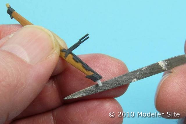
Care must be taken in preparing the wing struts as they are all individually numbered. I did find that the strut location pegs needed a quick file as the fit is pretty tight.
A small amount of filing is required for the strut locating pegs. This is only to get rid of the paint build up, as the tolerance is so precise on these kits. Believe it or not, all four struts have individual part numbers so make sure this are marked in the right order.
Before the top wing can be fixed in place it is always a good idea to clean out the holes already drilled for the rigging to avoid any snags during the next step. The instructions provide a very clear rigging diagram to follow, they even provide the scale dimensions of the rigging wires. The top wing will end up with around twenty individual strands of fishing line dangling underneath, so the best way to position the wing is to locate the the cabane (fuselage) struts into the holes first, then the outside wing struts. When I am happy with the wings position I can then cement these in place using liquid glue. Because this needs to dry over night its a good excuse to to relax and have a beer on a job well done.
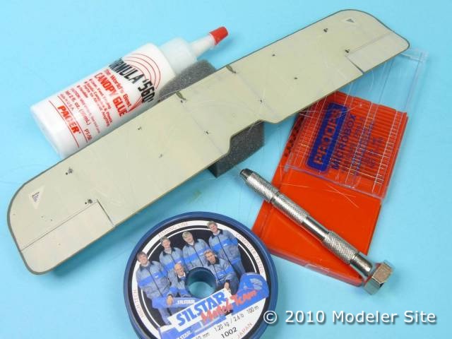
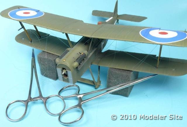
All the tools of the trade. Altogether there twenty individual ringing points to be drilled under the top wing. Then each line has to be glued in place prior to fitting to the rest of the model. Well every model has some mundane stages.
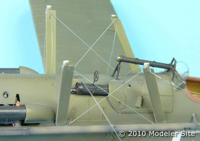
Once the centre section cross bracing is secured to the fuselage then holes are drilled into the top of the cabane struts and the rigging threaded through and glued with the spare end held under tension.
The next stage involves threading the rigging lines through the bottom wing holes using tweezers and Gater glue, which is a PVA type adhesive and any excess can be removed with a moist brush. Some form of weight is needed to keep the rigging under tension as the glue dries.
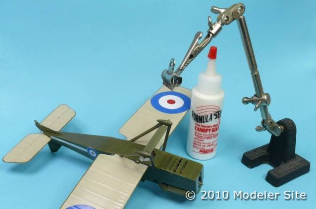
Once the undercarriage is in place the rigging can begin. A PVA based glue is ideal for securing the fishing line in its locating holes. Here the weight of the model is suspended from one line. Impressed?
There are no set rules for this process in fact I tried some thing different on the cross wires or stagger wires on the outer struts by simply tying a simple slip knot and glued in place. Its is how you interpret the rigging plans and the material you chose for the wires. All that matters is the end result and if it looks right to you.
Some rigging lines can simply be fixed in place by using a half hitch knot with a drop of thin super glue on top just make certain it does not become loose.
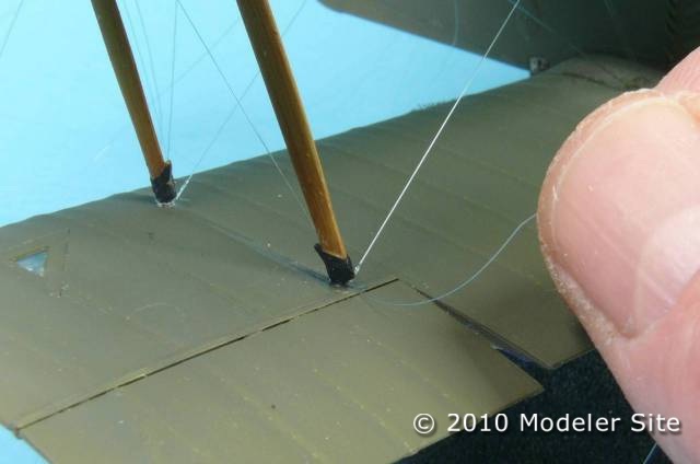
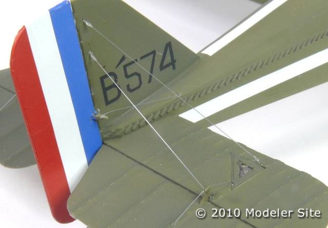
Much of the rigging is inserted through pre drilled holes in the lower wing and secured again using PVA adhesive. Due to the small amount of give in the fishing line, this method acts like actual rigging keeping everything taught with no sagging.
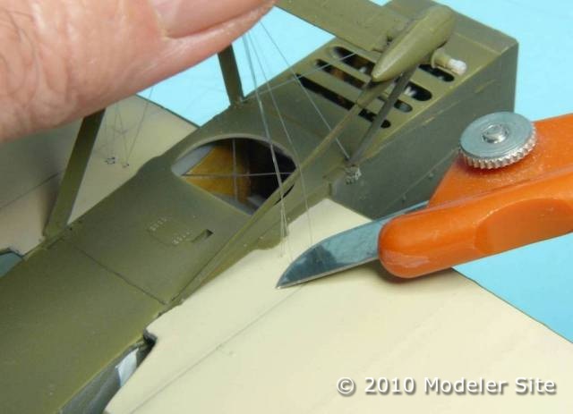
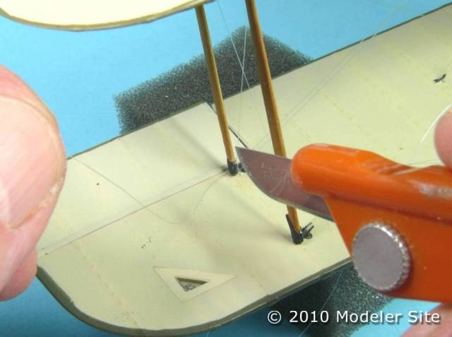
To complete this stage all that is left is to cut the excess line flush with the exit hole using a fresh scalpel blade, and a touch up with paint here and there. See nothing to it! One thing that always surprises me, is just how robust the whole assembly becomes, just like the real thing.
Any loose ends are cut using a scalpel blade, then the exit point can be touched in with the original paint.
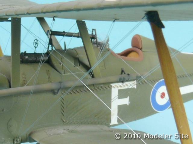
By gluing a couple of lines at a time the effect will soon begin to look like this. Looks complicated but believe me it isn’t, but very satisfying when finally finished.
Final details
This is my first foray with the Wingnut brand, it wont be my last. Just looking at the box art you just know something special resides inside. Even peering at the sprues through the plastic bags the detail is very apparent.
I did find the instruction pamphlet needed a little time to get used to as they are totally different to other manufactures endeavours. The inclusion of relevant colour photographs of restored SE 5 aircraft along side various stages of the build is a great help and an idea which I am sure other manufactures will soon follow.
Finally the inclusion of Cartograph decals to finish off a superb model in fact the best I have ever come across and a pleasure to build. Go on treat yourself !
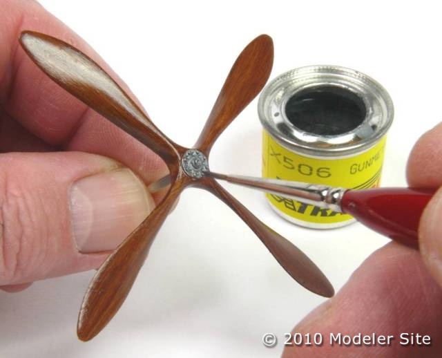
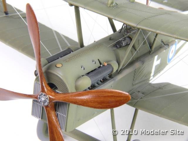
The final part, obviously this is left to last as it can easily be broken. I have to apologize as did intend to photograph half way to show the process. However I got so engrossed on getting it right I forgot, but it gives you some idea how effective oil paint graining can be.
by Michael Capell








Ted Gunn
A very informative set of photos especially around the cockpit and gun area. I am trying to draw a 3D model in Autocad and find this area is not clear from three view drawings. Also can you say what the D shaped access hole in the fuselage is for?
James ryan
Footstep for pilot access…
albion
The large D shaped hole in the bottom is for the ejection of the gun shells.
Garth
The large D-shaped hole in the bottom of the fuselage is, in fact simply to allow air to exit the engine bay after passing through the radiator. If it wasn’t there, there would be very little airflow through the radiator, since hot air would simply build up within the engine bay with nowhere to go.
The spent cartridge duct is the small rectangular aperture just behind this large opening. The vertical rectangular sectioned piece that fits in the cockpit (under the Vickers) gun is meant to exit there.
Leslie Beaumont
This is a fantastic model ,but is the use of PVA glue strong enough
to keep the rigging taut and not going slack. I would have thought super glue would have been preferable.